|
General
notes:
BEWARE
- The insides of the doors have sharp edges!
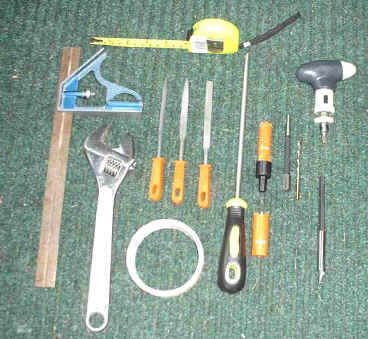
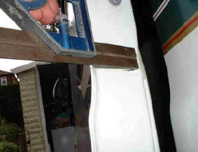
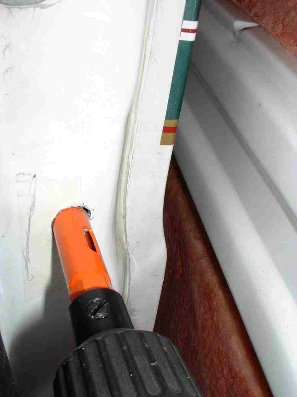
Allow
plenty of time to carry out this project and measure twice before drilling
any holes.
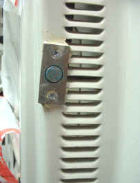
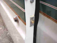
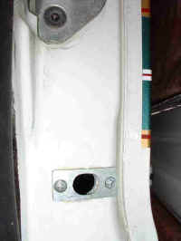
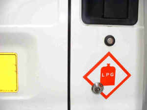
All
locks were installed with the spline in the centre hole Y and the splined
shafts need shortening. The additional splined rods must be fitted into
hole Z with their retainer tubing to prevent the lock being wound out too
far.
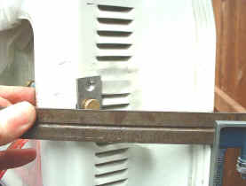
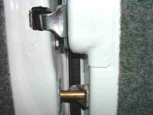
The
countersunk head screws supplied were not properly threaded (chipboard
screws?) to tighten into the thin metal and were replaced by M4
countersunk bolts, nuts and lock-washers which were very fiddly to
assemble inside the doors (a nut driver in the ratchet screwdriver with an
extension bar and some Blu-tac helped) or pan-head self tap screws for the
hole-plates.
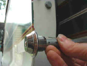
The
brass bolts for the front doors needed shortening to flush with the barrel
to allow the doors to close and operate with one turn.
The
rear door lock needs two turns to give sufficient throw of the bolt.
The
lock bolts were assembled so that they all locked with a clockwise turn of
the key.
File
the nib off one of the spare keys so that it can operate the lock and be
removed when testing the locks if the splines become mis-aligned with the
rackbolt before finally tightening the lock assembly retaining nut. |